Interpreting Plans and Elevations for the TMUA
Updated August 2025
This lesson covers the interpretation of plans and elevations of three dimensional shapes. Understanding how to reconstruct a solid from its two dimensional views is vital for spatial reasoning questions in the TMUA. You will learn to identify plan, front, and side views and represent hidden edges correctly.
Plans and elevations are two dimensional orthographic projections of a three dimensional object, representing the view from the top (plan), the front (front elevation), and the side (side elevation) using perpendicular lines of sight.
Representing Three Dimensional Objects in Two Dimensions
In mathematics and engineering, three dimensional solids are often represented on a two dimensional surface using a system called orthographic projection. This method projects the object onto three mutually perpendicular planes. For the TMUA, you must be able to move fluently between a 3D representation (such as an isometric drawing) and its 2D standard views. These views are defined as follows.
- The Plan: This is the bird's eye view of the object, seen from directly above. It captures the width and the depth of the object but tells us nothing about its height.
- The Front Elevation: This is the view from the front of the object. It captures the width and the height but contains no information about the depth.
- The Side Elevation: This is the view from the side (either left or right). It captures the depth and the height of the object.
To represent a solid uniquely, you generally need all three views. For example, a cylinder stood on its base would have a circle as its plan, but a rectangle as both its front and side elevations.
Understanding Hidden Lines
A critical convention in interpreting these drawings is the use of different line types to represent visible and obscured edges. Solid lines are used for edges that are visible from the specified direction. Dashed lines (or hidden detail lines) represent edges that exist but are hidden behind another face from that perspective.
When interpreting a diagram, you must look for these dashed lines as they often indicate a hollow section, a tunnel, or a step in the back of the solid. If a TMUA question asks for the minimum or maximum number of cubes that could form a solid given its elevations, the presence or absence of these hidden lines is often the deciding factor.
Visualising the Reconstruction
When given the plan and elevations, the best method for visualisation is to build the object mentally (or using a rough sketch) layer by layer. Consider a solid made of unit cubes.
- Use the Plan to determine the maximum 'footprint' of the object on the floor. Every square in the plan represents a vertical column of cubes.
- Use the Front Elevation to determine the maximum height of each column when looking from the front. If a square in the front elevation is units high, at least one cube in that front to back row must reach that height.
- Use the Side Elevation to refine the heights. A height of unit in a side elevation row means that no column in that left to right row can exceed a height of .
Worked Example: Calculating Volume from Elevations
Consider an object with the following views on a grid of centimetre squares.
Plan: A by square. Front Elevation: A by square. Side Elevation: A right angled triangle with base centimetres and height centimetres.
To find the volume of this solid, we first identify the shape. The plan and front elevation suggest a cuboid, but the side elevation shows a triangle. This indicates the solid is a triangular prism.
The side elevation tells us the cross section of the prism is a triangle with area square centimetres. The plan tells us the 'length' of this prism (how far it extends from front to back) is centimetres. Therefore, the volume cubic centimetres.
Continuity of Dimensions
A common check for the validity of elevations is to ensure dimensions are consistent across views. The width of the front elevation must be identical to the width of the plan. The height of the front elevation must match the height of the side elevation. Finally, the depth (width) of the plan must match the width of the side elevation. If these do not align, the set of drawings cannot represent a single rigid body.
Key takeaways
- The plan is always the view from directly above, showing width and depth.
- Hidden edges that are obscured from a certain view are represented by dashed lines.
- The volume of a prism can often be found by calculating the area of one elevation and multiplying by the corresponding dimension on the plan.
- Consistency between views is required: width, height, and depth must match across the three projections.
In the exam, use a small 'grid' method to solve cube problems. Mark the plan with the maximum possible height each column could be based on the front elevation, then cross-reference these with the side elevation to find the true maximum or minimum.
Do not confuse the plan with a cross-section. A plan is what you see looking from above the entire object, whereas a cross-section is a slice through the middle.
The relationship between elevations and 3D objects is a discrete version of the concept of 'projections' in higher dimensional geometry. Just as we project a 3D object onto 2D planes, mathematicians study how 4D objects would 'look' when projected into 3D space.
Worked Examples
Sketches of this object are made by looking at it from the right-hand side, from the front and from above. These sketches are called the side elevation, the front elevation, and the plan view respectively.
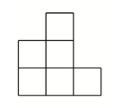
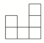
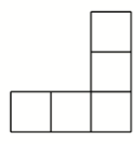
How many cubes were used to construct the object?
Frequently asked questions
What if an object has no dashed lines on any of its elevations?
This implies that every edge of the object is visible from those specific directions, or that the object has no internal hollows or recessed sections that would create hidden edges.
Can two different 3D shapes have the same plan and elevations?
Yes, it is possible for different objects to share the same standard views if the views do not capture certain internal details. This is why isometric drawings are often used alongside orthographic projections.
How do you handle curved surfaces like cones or spheres?
A sphere appears as a circle in all three views. A cone appears as a circle in its plan and as an isosceles triangle in its elevations. Curved surfaces do not have edges, so they are represented by their outer boundaries in orthographic projection.